Case 20: Thickness Monitor Placement
To obtain precise coating thickness we often use thickness monitor substrate to terminate deposition. These monitor pieces are usually stationary.
It would be convenient if a monitor substrate is positioned in the chamber such that its coating thickness matches that of the workpieces. With V-Grade 5, it is easy to find locations of this kind.
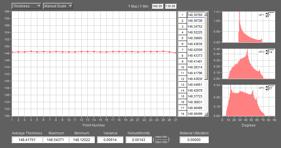
We again consider the model planetary-rotation coater with a pair of uncoupled masks. If the workpieces are flats that are leveled in the fixture, we obtain the thickness distribution shown below with an average thickness of 148.42 nm (for a material with density 3.15, i.e. magnesium fluoride).
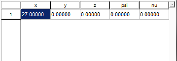
Now our task is to find a location in the chamber for a stationary substrate to collect the same thickness. There are unlimited possibilities for this. Here, we choose to place the monitor piece at the same height as the workpieces; and we choose to position it 2 cm farther away from the orbit center than the outer edge of the fixture. For this we can create a single-point surface in the Surface Coated panel:
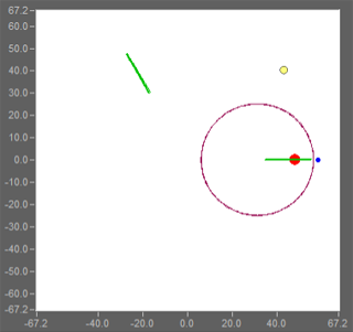
Now we adjust the azimuth angle (relative to the source) to match the thickness. To do so we can use the Orbit Initial Angle input in Computation Controls to specify this angle while setting the Primary rotation range to zero. Through a few trials we find that an angle of 42.61 degrees produces a very similar thickness: 148.43 nm. The diagram below (chamber top view) show the location of the monitor.
Clearly one can find many other locations in the chamber where a monitor substrate collects the same thickness as the workpieces, particularly if the orientation of the monitor piece is allowed to vary. The monitoring system in use may ultimately determine where and how a monitor piece should be placed.