Case S13: Dual rotary magnetron source for large substrates
This example demonstrates modeling of thin-film deposition on a large substrate (1 meter wide) employing a dual rotatory magnetron source. The program used is V-Grade 5S Plus.
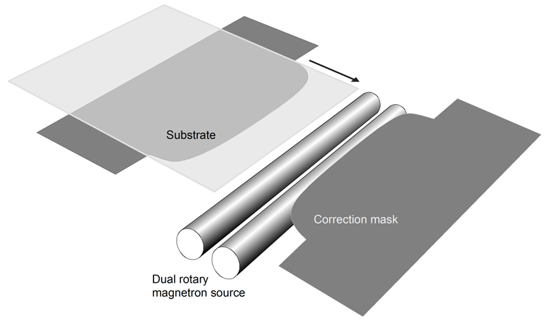
The deposition process is illustrated in the schematic drawing below. Each sputtering surface is a part of a cylinder, 16-cm in diameter, which rotates about its own axis. The length of the sputtering track is approximately 120 cm. Users can compose sources of this type in an independent spreadsheet program and then import them into V-Grade 5S. (A dual rotary magnetron source is not in the standard library that one can spawn in V-Grade 5S. Tin Model offers expanded libraries for additional source types and surface types - please contact us for your needs.) The substrate moves at a constant velocity in a direction perpendicular to the cylinders.
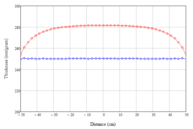
Typical to deposition geometries of this kind, the film thickness across the width of the substrate has a bow-shaped distribution, as shown by the red points in the thickness plot below. The associated non-uniformity is +/-5.1%. A longer source can reduce the non-uniformity to some extent. To achieve good thickness uniformity, less than 2% for example, correction masks must be employed.
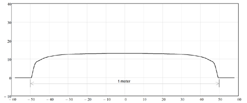
Given the geometry of the deposition process and the vapor plume function of the target, one can design an effective correction masks with the help of V-Grade 5S. Shown below is an optimized mask for a vapor plume function that is characteristic of metal targets. The thickness distribution with the mask is shown by the blue points in the above diagram. The corrected distribution has a non-uniformity of +/-0.15%.
To obtain an optimized mask for a process, one must first know the nascent plume function of the target, which can vary significantly from material to material, to a reasonable precision. The plume-fitting function of V-Grade 5S can be employed to determine the plume function of a target from an experimentally measured thickness distribution, be it from deposition on a static or a moving substrate.
A consequence of installing correction masks is a reduced collection of the material vapor. (Included in the computation of V-Grade 5S is the vapor collection efficiency.) The vapor collection efficiency with the masks is 63.0% (63.0% of all the material vapor lands on the substrate), compared to 69.7% without masking.
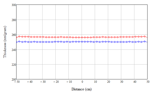
Frequently, it is important to know how the thickness uniformity should vary due to change of material or erosion of the targets. In V-Grade 5S, one can predict these changes quantitatively: the evolution of the plume function, which is usually the main cause of uniformity change, follows a predictable behavior that can be adequately described by a polynomials of the cosine. In this case, we can also factor in the reductions in the radius of the target due to material removal. The following diagram shows the predicted thickness distribution before and after erosion of the target: the thickness uniformity evolved from +/-0.15% for a fresh target to +/-0.28% for a severely eroded target, shown by the red points.
In this particular process, the fixed mask yields good thickness uniformity for significant variation in vapor plume (associated with material differences or target erosion) -- this is not usually the case in many other geometries. The modeling indicates that with this geometry one can reasonably expect to achieve thickness uniformity around +/-0.5% for a range of materials and under varied states of target erosion.
As usual, the thickness values shown in the above diagrams are absolute values: they are in units of 'nanometers per gram of target material removed". These values can be used to budget material consumption for a given job.