Case S4: Magnetron with Planetary Fixturing
The marriage of magnetron sources and planetary-rotation fixtures can bring advantages in load capacity and thickness uniformity.
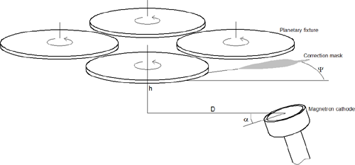
In this example we analyze a coater having four planetary-rotation fixtures as shown in the above diagram. The radius of the planets is 10 cm; the radius of the orbit is 14.3 cm. The planar magnetron cathode is assumed to be the same as the previous cases: the erosion track is a ring with a diameter of 2 inches.
As in the case of simple-rotation fixture, the thickness distribution in this configuration is affected by the characteristics of the angular distribution of the sputtered particles. We first analyze the case that the target exhibits a heart-shaped angular distribution of the sputtered particles, which is usually associated with a fresh target. If the objective is an arrangement with material-collection efficiency around 25% we find an arrangement as follows:
D = 21.8 cm;
h = 10 cm;
alpha = 17 degrees,
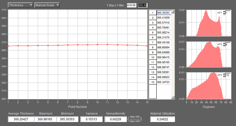
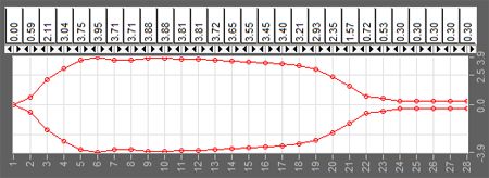
which yields a material collection of 24.6% and thickness uniformity of 0.23% over the radius of the planets. These results are shown in the V-Grade 5S screenshot below.
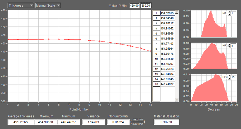
If the angular distribution of sputtered particles changes, which often occurs when a target becomes eroded after extended use, the thickness distribution will change as well. Let us examine a rather extreme case by assuming the angular distribution becomes wholly cosine. Changing the angular distribution for the source, V-Grade 5S yields 1.6% for thickness uniformity and 30.2% for material collection, shown in the screenshot below.
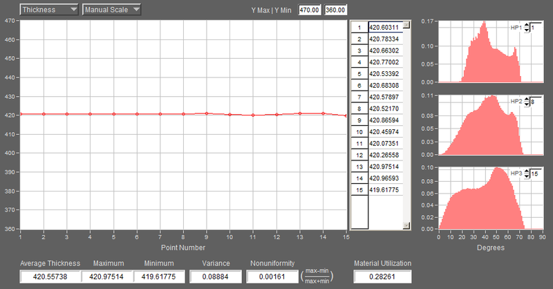
To correct the nonuniformity in thickness we can adjust the position and tilt of the cathode, or we can employ a correction mask. If we choose the latter method, V-Grade 5S allows you to fit a mask or masks in virtual coating experiments. The diagram below shows a mask that is positioned at a 25-degree angle (angle psi) measured from the cathode in the orbit circle. The mask design is obtained through a combination of manual fitting via virtual experiments and the automated optimization. With the mask, the uniformity is improved to 0.16%; the associated material collection is 28.3%. The corrected thickness distribution is shown in the second screenshot below.