Case S6: Magnetron coating spherical lenses
PVD coating of lens surfaces, whether in sputtering or evaporation mode, usually requires re-optimization from processes that are optimized for flat substrates. In this example we examine the coating of spherical lenses in a planetary-rotation-tooled magnetron sputtering chamber.
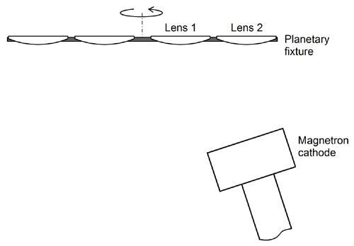
First, we place two spherical lenses, Lens 1 and 2, along the radius of a fixture that makes planetary rotation in a chamber with a planar magnetron source, as shown in the schematics below. The lenses are 7-cm in diameter and 15-cm in radius of curvature. The position and tilt of the magnetron cathode has been optimized for flat substrates mounted on the fixture.
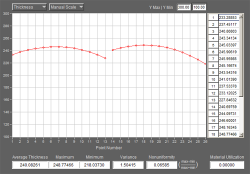
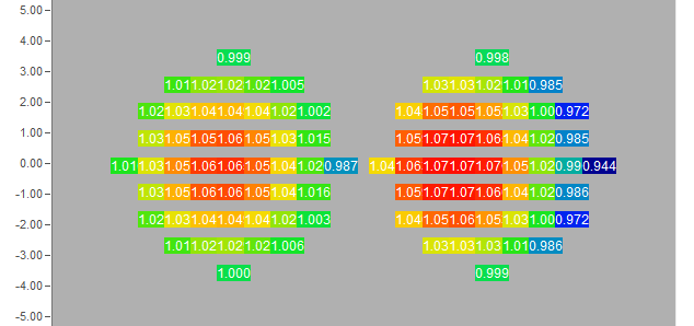
Carrying out a virtual experiment with V-Grade 5S, we obtain the thickness distributions on the two spherical surfaces, displayed in the screenshots below. (The V-Grade 5S thickness maps label each sampling point with either the absolute thickness values or the normalized thickness values. Here the normalized thickness values are shown.) Similar to the situation with evaporation-source coating (see case study #2), the thickness distributions on the two lenses are very different. The most pronounced is the asymmetry in thickness with respect to the centers of the lenses, especially for Lens 2. This asymmetry can be detrimental to its optical performance.
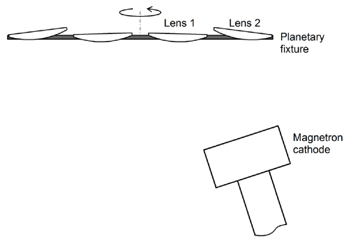
An effective way of improving the results is to terrace the lenses, i.e. repositioning and pivoting (see case #3 and #4). With V-Grade 5S, finding the best terracing is as easy as carrying out a few virtual experiments. After several virtual-experiment trials, we arrive at the following terracing arrangement:
Lens 1: Pivot angel = -1.5 degrees;
Lens 2: Pivot angel = -7.0 degrees; Z-translate = 0.5 cm.
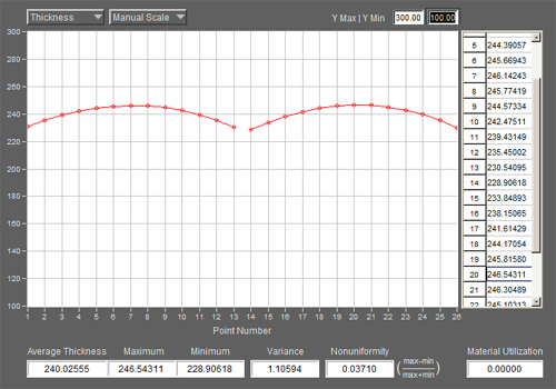
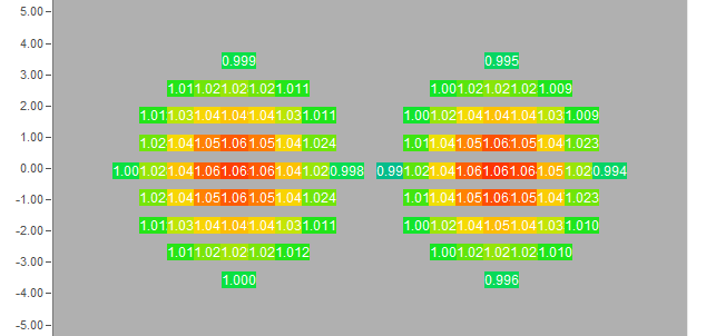
With the terracing, the thickness asymmetry is largely eliminated. In addition, the thicknesses at the centers of the two lens are now equalized. The new thickness distributions are displayed in the screenshots below.