Get the Most out of Your Coating Equipment
"Get the most out of your coating equipment" means achieving the best of objectives, which may be different from one job to another. Some common objectives are thickness uniformity, collection efficiency of source materials, adherence to certain vapor striking angles; load capacity and process stability.
Here are some common and lesser-known techniques one may consider while optimizing a coater for thin-film manufacturing:
1) optimization of source location;
2) terracing of substrates, or workpieces in general;
3) optimization of correction masks;
4) maintaining a suitable evaporation rate; and
5) tilting the axis of rotation, where possible.
Optimization of source position
Location of an evaporation source has major impact on the thickness distribution and on the material collection efficiency. Most coaters allow repositioning of evaporation sources. This technique is, however, often underutilized because of the lengthy process of trials and errors.
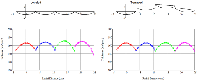
Terracing the workpieces
Terracing is an effective technique for achieving good thickness uniformity, without engaging any correction masks. In the technique, thickness uniformity is achieved by placing workpieces at varied heights and/or facing angles. This technique is rarely practiced because its outcome is hard to predict and even harder to optimize without the aid of a numerical simulation tool.
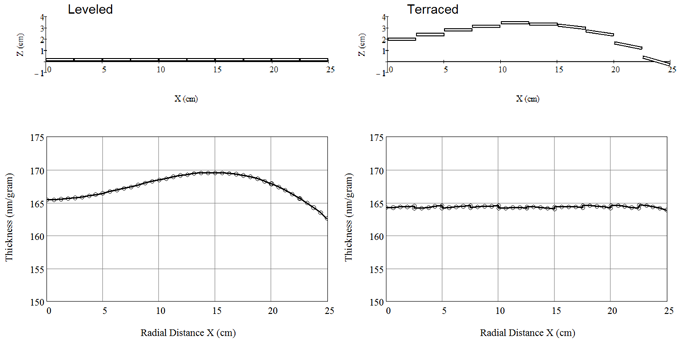
Suppose that you are using the model planetary-motion coater that we analyzed above (with D=48 cm and H=32 cm) to coat flat surfaces of 2.5 cm in diameter. And suppose that you lay ten such substrates in the plane of the planet along a radius. According to the previous analysis the thickness uniformity would be U= +/- 2.0%. Now, let us terrace the substrates: we move the substrates in the z-direction (which coincides with the rotation axis of the planet fixture) for various amount to minimize the inter-substrate nonuniformity. To further improve the results, we can pivot some of the substrates so that the intra-substrate nonuniformity can be reduced as well. After a few numerical trials with V-Grade 5, we find that the placement of the substrates summarized in the following table yield a much improved thickness uniformity.
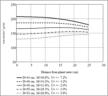
The diagram below shows how the lateral location of a source (measured from the orbiting center), D, affects the material-collection efficiency M and thickness uniformity U, in a model planetary-motion coater, in which three substrate carriers, 25 cm in radius, orbit on a radius of 31 cm. The carriers are 32 cm above the source.
The smallest thickness nonuniformity of (+/-) 2.03%, across the entire carrier surface, is found when D=48 cm. A greater D worsens the uniformity and the material collection, whereas a smaller D worsens the uniformity but raises the material collection.
When the material density is known, V-Grade 5 gives quantitative accounts of these relationships. Here the source material is assumed to be magnesium fluoride with a density of 3.15 grams/(cubic centimeter). The Y-axis values are in unit of nanometers per gram of material evaporated.

The resultant thickness distribution is shown in the diagrams below: the left side is the result before terracing; the right side is that after terracing. The thickness nonuniformity has been reduced from +/- 2.0% to +/- 0.23%. (With more aggressive terracing we can further reduce the nonuniformity below +/- 0.1%.) Unlike the use of correction masks, this uniformity is obtained without sacrificing the material collection: the thickness remains about 164 nm per gram of material evaporated (assuming a material density of 3.15 grams/cubic centimeter).
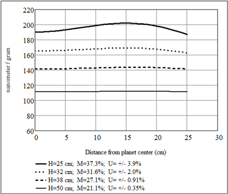
In some cases, the vertical position of an evaporation source can be adjusted, relative to the orbiting substrate carrier. The figure below shows how the vertical position of the source, H, affects the best uniformity achievable (in the absence of other techniques) and the associated material collection. Again, the material is assumed to be magnesium fluoride; the Y-axis is in unit of nanometer per gram of material consumed.
The technique of terracing is also useful in optimizing coatings on strongly curved surfaces, such as lenses. As an example, let us examine a job, in the same coater, of coating convex lens surfaces that are 7 cm in diameter and 8 cm in their radius of curvature.
Let us first level the lenses along a radius of the fixture, the first lens being centered in the fixture. For each lens we calculate the thickness at 13 points along its diameter (in the same direction of the fixture radius). As expected, there is significant nonuniformity in thickness due to the curvature of the surfaces, as shown in the left figure below. In the distribution, a disqualifying characteristic may be the severe asymmetry to the center of the lens, particularly in the two lenses close to the edge of the fixture (green and magenta).
To correct the asymmetry and the inter-lens thickness difference we now terrace the lenses. After a few numerical trials with terracing we arrive at a much improved situation: both the inter-lens difference in average thickness and the asymmetry are virtually eliminated, as shown in the right figure below. The largest translation is for the third lens: 2.3 cm; the largest pivoting angle is for the fourth lens: 7.5 degrees.
The concept of terracing is not new. The dome fixture in a single-axis coater may be considered a classical example of terracing. For more complex motion types, such as planetary-motion coater, a numerical simulation tool is essential for a successful implementation of terracing. Please view "Case Studies with V-Grade 5" for examples of terracing.
Correction Masks
Vapor-obstruction masks, or correction masks, can effectively correct thickness nonuniformity. A set of well-constructed and installed masks should 1) reduce the thickness nonuniformity below the tolerance of the job; and 2) block as little material vapor as possible. These two goals usually present themselves as tradeoffs, and the best compromise is not easily found with trials and errors.
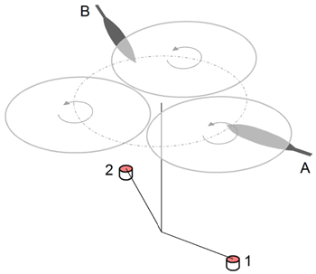
The task is made more difficult in situations, which we encounter frequently, that more than one mask is needed in a coater for depositing more than one material in a single pump down. In the example shown in the diagram above, the two masks, A and B, are deployed for two different material sources, 1 and 2. If the masks are positioned just below the coated surface, it is apparent that the material vapor from each source experiences some obstruction by both masks. This means that we must shape and test the two masks coordinately in order to obtain good results.
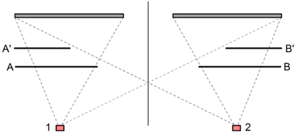
It is possible, and often advisable, to uncouple the masks by positioning them in a lower plane so that the lines-of-sight from a source to the fixtures (coated surface) are intercepted by one mask only. The diagram below shows an uncoupling of the masks: A and A’ obstruct vapor from source 1 only; B and B’ obstruct vapor from source 2 only. In effect, each evaporation source has its ‘own’ correction mask, which can be different from that of another source to account for any difference in the vapor plumes.
With the trials-and-errors method, attempts of optimizing masks seldom yield truly optimized masks. This is because the number of deposition runs and measurements necessary can prove too large and consuming. The use of a numerical simulation tool can be an enabling approach.
V-Grade 5 numerically simulates deposition with up to four masks, coupled or uncoupled. There are two modes available for mask optimization: manual optimization and automated optimization routine. Using the manual mode, we approach the problem the same way as trials and errors except that no physical depositions or measurements are needed – the software tells us accurately whether a change in the shape and/or positioning of a mask (or a set of masks) shall improve the outcome or not. It typically takes tens of these virtual trials to reach a much improved uniformity.
Manually adjusting the masks, however, does not usually leads to optimality. Further optimization can be made through the use of a mask-optimization routine provided with V-Grade 5. Powered by a proprietary algorithm, the automated optimizer adjusts 28 anchor points that define the shape of a mask.
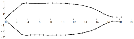
As an example, we will fit a set of masks for the same model planetary-motion coater that we analyzed previously. Let us assume that we have two evaporation sources that are separated in azimuth angle by 120 degrees. First, we manually fit a set of uncoupled masks, which are placed 22 centimeters above the sources. We choose to use a short mask: the shadow of a mask covers only slightly more than the radius of the fixture. (A long mask can cast a shadow that covers the entire diameter of the fixture.) After some trials-and-errors with manual adjustments, we arrive at the following mask shape; the tip of the mask (x = 0) is 34.5 cm from the center of the orbit. This mask yields a nonuniformity of +/- 0.5% compared to +/- 2.0% without masks.
Next, we use the above mask shape as the input in the automated optimization program. After several iterations we obtain an optimized mask shown in the diagram below. This mask further reduces the nonuniformity from +/- 0.5% to +/- 0.14%.
The thickness distributions resultant from the above two correction masks are compared with that of no mask, in the figure below. The more uniform thickness comes at a cost of reduced material collection. Without mask, the material collection is 31.6%; with the manually fit masks and the optimized masks the material collection reduces to 28.6% and 28.1%, respectively.
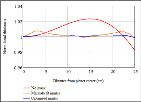
Incorporated in the mask-optimization program is a mechanism that automatically favors solutions that preserve the material collection. For this particular coater, the material collection of 28.1% with the optimized mask is the highest one can expect if such a stringent uniformity is desired.
A necessary feature of any mask is a handle for installation. Using the mask-optimization program in V-Grade 5, it is realized through the user-defined constrains to the shape. In the above example we set the minimum width of the mask handle at 7 mm.
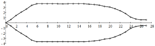
Coupled masks can be used as effectively as uncouple ones. In the same coater if we install masks close to the coated surface – 30 cm above the source (that is 2 cm below the coated surface), they are coupled. In other words, part of the material vapor from one source will be blocked by both masks on its path to the coated surface. The following diagram is the shape for such a coupled mask set (all dimensions are in cm). The mask tip is 29 cm from the center of the orbit. This coupled mask set yields almost identical results as the uncoupled ones: the thickness nonuniformity is +/- 0.16% with 28.1% material-collection efficiency.
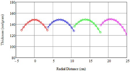
We should keep in mind that a mask set that is optimized for coating a flat surface may not produce desired results when curved surfaces are coated. Take, for example, the coater that we analyzed previously with the optimized masks (the uncoupled set from above). Now, let us place four convex lenses along a radius of the fixture as in the previous case. The resultant thickness distributions on the lenses are shown in the figure below. The masks only equalize the maximum thicknesses in each lens, but they do nothing in correcting the asymmetry in the intra-lens thickness variations. If we employing the technique of terracing here, with the masks, we can again correct the asymmetry. This, however, beckons the question whether correction masks should be employed at all for this job. In many situations, in fact, the use of correction masks is not the best approach.
Evaporation rate
Evaporation rate of a source can usually vary in a wide range. Physical properties desired from the deposited material may dictate a suitable evaporation rate of the source. In regard solely to thickness uniformity one also need to pay attention to the evaporation rate employed.
There are two main considerations when we choose an evaporation rate: 1) the spatial distribution of the vapor plume is, to some degree, dependent on the evaporation rate of the material; 2) To produce very thin layers with good thickness uniformity, the evaporation rates must not be too high.
It is well known that in a vacuum the vapor cloud, or vapor plume, from an evaporating source can be modeled with the Knudsen cosine law:
where Flux is measured on the surface a source-centric hemisphere; C is proportional to the evaporation rate and n is a vapor parameter that can vary from one material to another and be dependent on the evaporation rate. The larger the n the more focused the vaper plume is – its value falls off more quickly as theta increases. Studies show that high evaporation rates tend to create focused plume. Although n values in a wide range have been reported, for modest evaporation rates the value of n is most commonly in the range of 1.5 to 2.
In all the studies shown previously we have used the same value: n =1.8. Now let us vary n and show its effects to the thickness uniformity in the model system that we analyzed previously: the planetary-motion coater with the uncoupled and optimized masks. The figure below shows how the thickness distribution changes if n deviates from 1.8.
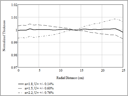
The tight thickness uniformity can be regained if we re-optimize system with any of the above-mentioned techniques, or a combination of them.
The above analysis illustrates that, for coating results to be reproducible, it is important to maintain the vapor plume characteristics under which a system is optimized. This usually means using the same evaporation device and maintaining the same evaporation rate.
Notes on very thin layers:
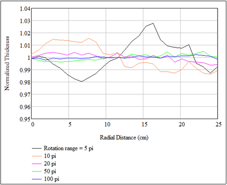
Special attention should be given to the evaporation rate when very thin layers are to be deposited. This is because with complex motions of a fixturing, such as the planetary movement, stable and uniform thickness distribution can only be achieved through an accumulation of a large number of rotations. This is especially true if correction masks are in use.
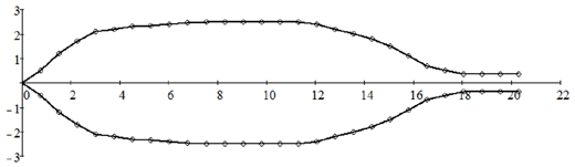
Consider the model planetary-motion coater with the uncouple masks which we analyzed previously. We now want to examine what should happen to the thickness distribution after a planet (work holder) completes these limited numbers of orbiting revolutions: 2.5 (5 pi), 5, 10, 25 and 50 (100 pi). The figure below show that after a small number of revolutions the thickness distribution is highly irregular and unstable. This is because that within a small number of revolutions:
1) the surface points are yet to journey through the space, prescribed by the planetary-motion
gearing, for a good averaging, and
2) the surface points have too few chance encounters with the shadows of the masks.
In fact, this simulation suggests that a minimum of 50 to 100 orbiting turns are necessary to achieve a stable and uniform thickness distribution. To deposit very thin coatings, one must keep the evaporation rate low enough so that the final thickness is built in no fewer than 50 to 100 orbiting turns.
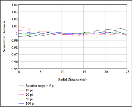
The above suggests that, in the absence of correction masks, a stable thickness distribution should be reached within fewer orbiting revolutions. We can test this with a case that we presented previously: the coating of 10 flat substrates with the technique of terracing (without correction masks). Again, we record the thickness distribution after the completion of 2.5, 5, 10, 25 and 50 orbiting revolutions. The results, shown in the figure below, demonstrate that the thickness distributions are indeed much less irregular and stabilize to the final and uniform distribution in fewer orbiting turns.
It is clear now that the technique of terracing is more friendly to coating of very thin layers than correction masks.
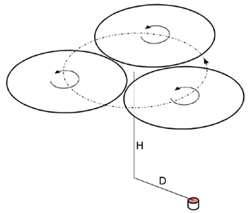
Tilt of Planet Axis
In some planetary-motion coaters, the rotation axis of a planet (work holder) can be set at an angle with respect to the orbiting axis, as shown in the diagram below. This extra degree of freedom is a precious resource – it can endow a coater with greatly expanded capabilities.
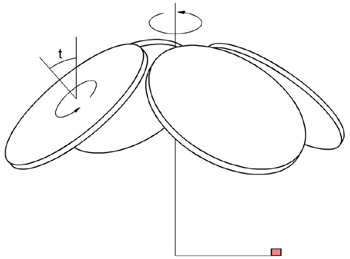
As an example, we will show that by tilting the planet axis high material collection can be achieved while maintaining thickness uniformity. We consider a coater with similar geometry as the model system that we analyzed previously except that the rotation axes of the planets are tilt from the orbiting axis by 43 degrees, as shown in the diagram above. On the same orbiting radius (31 cm) we can now accommodate four fixtures of the same radius (25 cm). Through optimizing the source position we obtain the following results (without the aid of any mask):
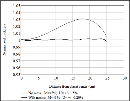
Peak-valley nonuniformity (across the entire radius): +/- 1.5%;
Material collection: 45% .
Next, we introduce a pair of masks that are shaped through the mask optimizer of V-Grade 5. With the masks, we obtain the following:
Peak-valley nonuniformity (across the entire radius): +/- 0.20%;
Material collection: 43%.
The thickness distributions across the fixture radius, with and without masks, are exhibited in the figure below.
We notice that the material collections here are substantially higher than what we obtain from the more traditional planetary-motion for comparable thickness uniformity.
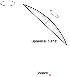
To give another example, we replace the flat planets with spherical domes, schematically shown below. Again we assume a 43-degree tilt angle for the planets. The radius of the sphere is 60 cm. By slightly relocating the source we obtain a combination of extraordinary uniformity and material collection: the peak-valley nonuniformity is +/- 0.20%; material collection is 50%. This is obtained without any correction mask!
Tilting the planets, one may find many other configurations that yield good results. It can be said that tiltable planets offer tremendous advantages. Wherever available, planet tilting should be fully exploited.
Copyright © 2015-2025 Tin Model LLC. All rights reserved.