Newsletter issued in September 2018
How to Shape and Optimize a Correction Mask
Design and optimization of a correction mask for a thin-film coating system with planetary rotation can be a very time-consuming and frustrating process. The end result is often unsatisfactory. The difficulty stems from the fact that the width of a mask at one radial position affects thickness distribution over a range of radius. In other words, the relationship between a mask shape and its resultant thickness distribution is convoluted.
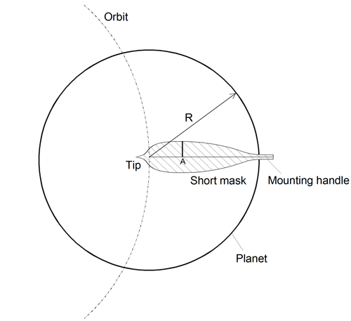
Although trial-and-error is the usual approach, this is not to say that there are no analytical clues that can help us. In the example below we will show how a mathematical analysis can help us in crafting a trial mask and how optimization of a mask may best be approached. We will now consider a "short mask", which casts a shadow mainly on the radius of the planet (as opposed to a "long mask" which casts a shadow over the entire diameter).
The manner of the planetary-motion tells us, referring to diagram below, that the width of the mask at radius A affects all the points with radius greater than A but none of the points with radius smaller than A. This observation suggests a strategy: one should start by trimming the thickness at the center of the planet and work outward to the edge.
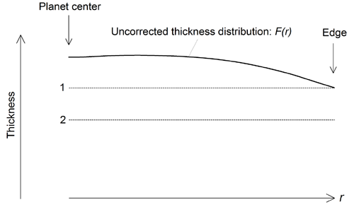
We still need to set a target: the amount of thickness to trim. Owing to the same observation, we know that the target shown by line 1 (below) is impossible to attain: the trimming of thickness near the planet center will unavoidably reduce the thickness at the planet edge. A more realistic target would be line 2. The thickness difference between line 1 and 2 is a matter of specific geometries involved, a good guess of it can come from experience and further analysis. A rule of thumb is that target line 2 is lowered from line 1 by an amount that is similar to the excess thickness near the center of the planet compared to the edge.
Mathematical analysis can provide further guidance to shaping of a correction mask. It can be shown (unpublished result of Tin Model LLC) that the half-width of a mask, w, as a function of the radial position r is, to the first-order approximation, determined by the following equation:
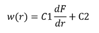
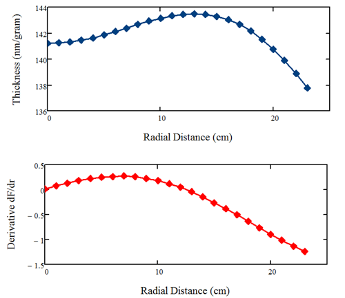
where dF/dr is the derivative of the uncorrected thickness distribution F(r). By adjusting the two constants C1 and C2, one can arrive at a first (rough) mask design for trial. In the following, we will demonstrate a process of shaping a correction mask with the suggested method for a modeled thin-film deposition system. The coating system features an evaporation source that coats a planet, 25 cm in radius, orbiting on a 31-cm-radius circle. The uncorrected thickness distribution is shown by the blue line in the figure below; the derivative of the blue curve is the red curve, which is simply the value differences between adjacent points of the blue curve. According to the above equation, a mask shaped like the red curve is for correcting the blue curve, good to the first order of approximation.
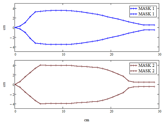
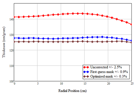
Armed with this knowledge we craft a first trial mask shown below in blue. The main and center portion of the mask is shaped by applying the derivative curve (above) in the equation and adjusting the two constants; the left end is tapered to a point through educated guess; the right end is made to maintain a finite width for mounting. This mask performs relatively well: it reduces the thickness non-uniformity from +/-2.5% to +/-0.9%.
To optimize the mask, we make use of a mask optimization routine in V-Grade 5S (a product of Tin Model LLC). Through iterations we obtain a mask shown below in brown color. This mask further reduces the thickness non-uniformity to +/-0.3%, which is the best one can expect from coating in this geometric arrangement. A comparison of the thickness distribution for the three cases is shown below in the lower graph.
We have shown that a mathematical analysis can help us in crafting a first trial mask. Optimization of a mask (to meet a stringent specification) requires a large number of iterations which are preferably, if not necessarily, accomplished through numerical simulation.
Additional Remarks
1. One may question the validity of using a numerically modeled coating system for this article. A well constructed numerical model can faithfully mimic real coating systems to great details. Numerical modeling tools such as V-Grade 5 series (Tin Model LLC) have proven very realistic in predicting the behavior of PVD coating systems, whether it employs an evaporation source or a sputtering source.
2. Crafting a first trial mask takes a fair amount guess work even with analytical guidance, as demonstrated here. The modeling tool itself does not make your guesses any better, but it does make testing the mask painless - you only need to press a few buttons on your computer. The real benefit of using such a numerical tool is in optimization of correction masks. The process of deriving MASK 2 from MASK 1 (above) takes a large number of iterations. It is impractical for such iterations to be carried out with a physical deposition system and metrology, considering the time and expenses that would require. This is why truly optimized correction masks are rare in the industry.
3. It is easy to appreciate that a correction mask can only be optimal for a specific vapor plume emitted by your source. To effectively optimize correction masks, V-Grade 5S is equipped with a plume fitting function: it characterizes a vapor plume with a 3-term polynomial of the cosine, through a least-square fitting of experimental data. An efficient process for obtaining an optimized mask would be:
-- deposit a film without mask
-- measure thickness distribution
-- determine the vapor plume with V-Grade 5S
-- craft a first trial mask using the analytical guidance
-- optimize the mask in numerical modeling
-- make and install the mask in your system
-- test and validate the mask
-- make any final adjustments if necessary.
4. A penalty of employing correction masks is the waste of material vapor. In this example, the vapor collection efficiency is 32.3% without any correction mask; it reduces to 29.1% and 28.6% for the first mask and the optimized mask, respectively.
5. The use of correction masks is one of several ways of achieving thickness uniformity. Other methods include substrate terracing, optimal placement of sources and unique forms of substrate rotation. Numerical modeling tools, such as V-Grade 5S, allows you to evaluate all these options. In some cases, one can find solutions that maintain thickness uniformity even when the vapor plume changes.
For further information or comments please contact Tin Model LLC. If you missed previous newsletters please visit TinModel Newsletter Archive.
© 2018 Tin Model LLC, 2285 Massachusetts Ave.
Cambridge, Massachusetts 02140, U.S.A.
Phone: (857)498-9723
www.tinmodel.com