Case S3: Correction of thickness nonuniformity
To correct thickness uniformity in sputtered thin-film materials we can adopt any one, or a combination, of the following techniques:
1) Reposition the source;
2) Adjust the source tilt;
3) Install correction masks; and
4) Terrace the workpieces (when coating small parts).
Except for the source tilt, these techniques are applicable also to evaporation-mode PVD, which are explored in the case studies for V-Grade 5.
Here we focus our attention to the problem encountered in the previous case (Case S2): the deteriorating thickness uniformity as the target gets more and more eroded.
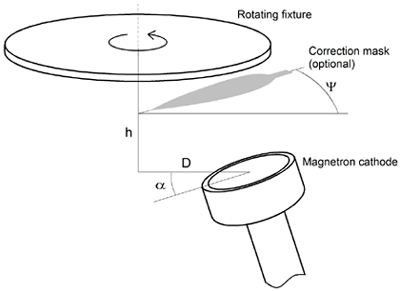
Employing method 1 and 2 can be a viable solution. V-Grade 5S can help you quickly determine how to adjust the three geometric parameters, h, D and alpha, to regain the thickness uniformity. For some chambers, however, the position and tilt of a cathode can be difficult to adjust. In such a situation, deploying changeable correction mask(s) can be more convenient.
V-Grade 5S allows you to manually fit correction masks (up to 4 of them) via virtual coating processes. There is also an automated routine that optimizes correction masks with user-defined constraints.
Here we position the mask at a 35-degree angle from the center of the cathode in the rotation circle. This arrangement has two advantages: 1) the mask can be shared with a similar target that is located 70 degrees in the circle from this target; and 2) material that flakes off the mask does not fall onto the target (if the cathode faces up).
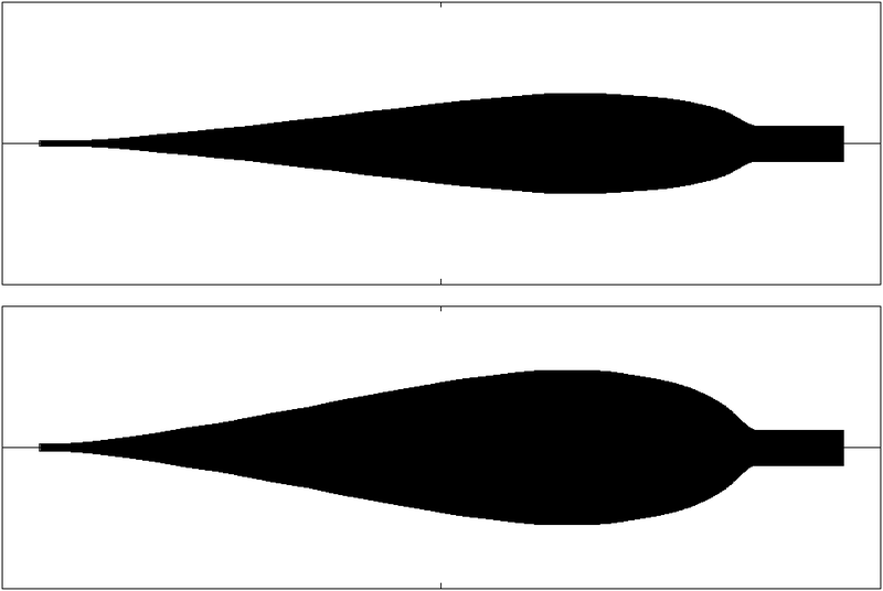
With a combination of manual fitting and automated optimization we obtained two masks, one for a new target that exhibits a heart-shaped angular distribution of the sputtered particles; the other for an eroded target that exhibits a cosine angular distribution. The shapes of these two masks are shown in the diagram below. The masks are pointy at their inner ends and have a handle at the outer ends for mounting. These practical features are obtained by imposing constraints during the optimization process.
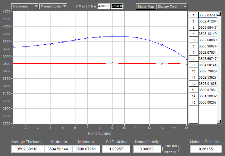
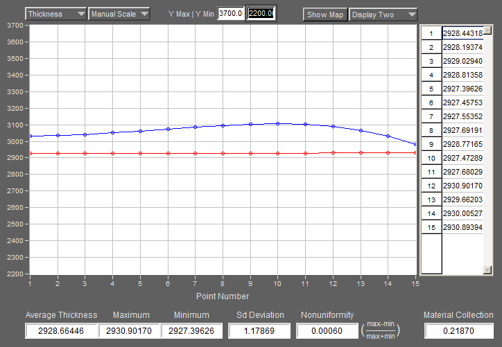
The improvements in thickness uniformity for both the new and eroded targets are shown in the figures below. For the new target, the mask reduces the nonuniformity from 2.0% down to 0.060%; the associated material collection efficiency with mask is 21.9%.
For the eroded target, the mask reduces the nonuniformity from 4.1% down to 0.063%; the associated material collection with mask is 26.2%, which is markedly higher than the new target.
The unit of the thickness displayed is "nm/gram": nanometers per gram of material removed from target. The target is assumed to be silicon with a density of 2.33 gram/cm-cube.
With V-Grade 5S, one can design and fabricate a series of masks that are easily changeable to maintain thickness uniformity throughout the progression of the target erosion.